 Window comparator using op amps" width="412" height="277" />
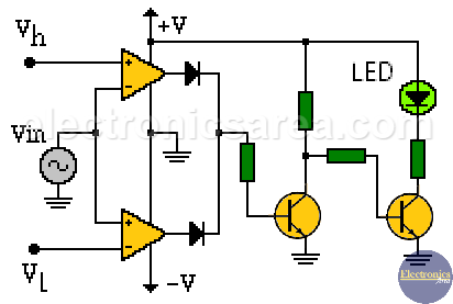
The voltage level to be reported (Vin) is applied to the inverting input of the op amp that controls the upper limit (Vh) and also to the non-inverting input of the op amp that controls the lower limit (VL).
By setting the upper limit voltage and lower limit voltage at terminals Vh and Vl, the range of voltages in which the window comparator output will be active is defined.
 Window comparator using op amps" width="412" height="277" />
Window comparator using two comparators or two op amps.
LED will only light up when the outputs of the two op amps are at a low level indicating that the Vin signal is within the range of allowable voltages. Then the first transistor will be in its cutoff region and function as an inverter, and the second transistor will enter its saturation region, turning on the LED.